
Cracking the Code of Flow-Induced Vibration: How Coupled Simulation Solved a High-Pressure Challenge
When engineers push process plants to higher capacities, unseen forces can quietly threaten the integrity of critical components. One such challenge—flow-induced vibration (FIV)—can turn an apparently minor design oversight into a costly reliability issue. At Sequence, we recently tackled this head-on using coupled Multiphysics simulation, blending Computational Fluid Dynamics (CFD) and Finite Element Analysis (FEA) into a powerful diagnostic and design tool.
The Problem: Cracks Beneath the Surface
During a methanol plant debottlenecking project, engineers increased the flow rate through high-pressure (HP) steam lines to boost throughput. Routine checks in preparation for a plant turnaround flagged several thermowells—the slender probes that house temperature sensors—as potentially at risk of FIV, based on the ASME PTC 19.3 Thermowells guideline. Soon after, inspections confirmed fatigue cracks at the thermowell bases, validating the initial concerns. However, the usual decoupled vibration assessments couldn’t fully explain the failures. The culprit turned out to be wake interactions and lock-in resonance among clustered thermowells positioned immediately downstream of a pipe elbow—conditions far more complex than any simple frequency comparison could capture. Also, how were re-rating ambitions going to be met with already stretched infrastructure.
Such challenges are increasingly common as industrial plants push for higher efficiency. In this case, unsteady flow conditions and coupled fluid-structure effects produced complex excitation patterns, demanding an advanced diagnostic approach that could handle turbulence, vortex shedding, and structural resonance all at once.
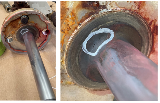
Figure 1.
Example of thermowell cracking in HP steam line (ASME FEDSM2025-158525, Fig. 1)
A Smarter Approach: Coupled Multiphysics Simulation
To get to the root cause, the engineering team combined fluid–structure interaction (FSI) within STAR-CCM+® and validated results using Abaqus® FEA. This fully coupled CFD–FEA approach simulated the turbulent, unsteady flow field, structural vibration modes, and feedback between them—something traditional methods cannot do. In the CFD domain, a Detached Eddy Simulation (DES) captured detailed wake structures and vortex shedding downstream of the elbow. The results revealed high-energy regions and fluctuating forces on the thermowells, which were then coupled into the structural solver, showing strong resonance near 400 Hz—the natural frequency of the unsupported thermowells.
This workflow provided engineers with direct insight into how flow turbulence, pressure pulsations, and structural stiffness combined to create damaging vibration.
Figure 2.
CFD velocity magnitude along HP steam line centreline, showing wake interference and vortex structures (from original Fig. 11–12).
Design Optimization: Support That Makes the Difference
Using the FSI insights, the thermowells were redesigned with a support arrangement that increased stiffness and natural frequency, avoiding the problematic lock-in region. Subsequent simulations confirmed a dramatic reduction in stress and displacement amplitudes. The improved design not only eliminated resonant vibration but also extended fatigue life—restoring confidence in the upgraded steam line and helping the client meet production goals without sacrificing reliability.
The supported design effectively decoupled the natural frequency of the thermowell from the dominant vortex shedding frequency. This shift broke the feedback loop responsible for self-sustaining oscillations. Quantitative results from FEA showed stress range reductions exceeding 60%, with clear correspondence between predicted stress hotspots and previously observed fatigue cracks. The upgrade proved that smart design changes informed by physics-based simulation can deliver measurable safety and performance benefits.
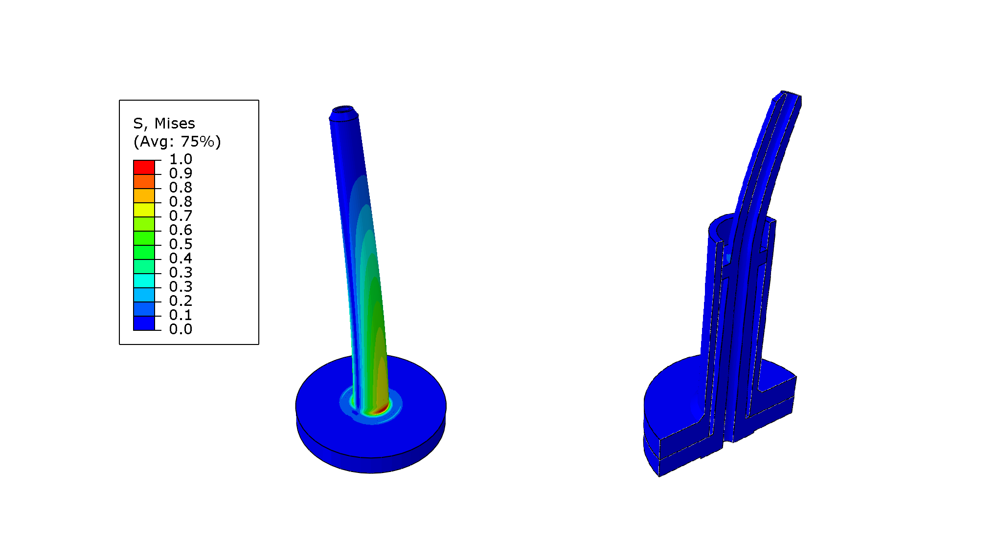
Figure 3.
Comparison of predicted normalised stress distributions for unsupported and supported thermowells (ASME FEDSM2025-158525, Fig. 17).
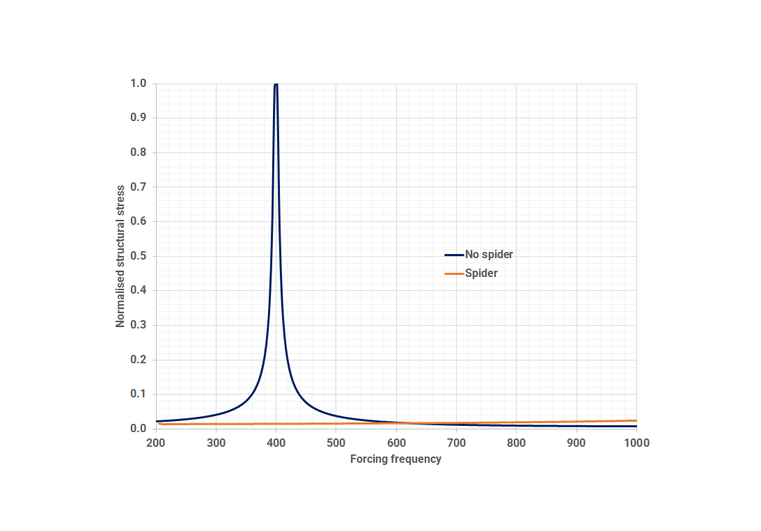
Figure 4.
FEA Frequency response predictions of stress range for unsupported and supported thermowells (ASME FEDSM2025-158525, Fig. 18)
The Takeaway: Integration Beats Approximation
This case demonstrates that coupled CFD–FEA Multiphysics simulation isn’t just a research exercise—it’s a practical engineering tool that saves time, reduces risk, and strengthens assurance during plant upgrades. By capturing the true physics of fluid–structure interaction, engineers can identify complex vibration mechanisms early, evaluate design mitigations virtually, and provide defensible assurance models. The approach also enables predictive maintenance planning, helping operators anticipate component wear before it becomes critical.
As industrial systems evolve and demands increase, integrated simulation will remain central to safe and efficient design—bridging the gap between theoretical prediction and real-world performance. Projects like this underscore the growing importance of digital twins, where virtual models continuously mirror plant behaviour, enabling smarter decisions and reducing downtime.
References
P. Bosauder, E. Primera, and A. Rodríguez-Prieto, “Coupled Multiphysics Simulation for Root Cause Analysis of Process Flow Vibrations in Piping Systems,” in Proc. ASME 2025 Fluids Engineering Division Summer Meeting (FEDSM2025), Philadelphia, PA, USA, July 27–30, 2025, Paper No. FEDSM2025-158525.
Versteeg, H. K., & Malalasekera, W. An Introduction to Computational Fluid Dynamics: The Finite Volume Method. Pearson Education, Harlow, UK, 2007.
Çengel, Y. A., & Cimbala, J. M. Fluid Mechanics: Fundamentals and Applications. McGraw-Hill, New York, NY, USA, 2014.
ASME, Boiler and Pressure Vessel Code, Section VIII, Division 2: Rules for Construction of Pressure Vessels, Part 5: Design by Analysis, The American Society of Mechanical Engineers, New York, NY, USA, 2023.
Young, W. C., & Budynas, R. G. Roark's Formulas for Stress and Strain (7th ed.). McGraw-Hill, New York, NY, USA, 2002.
Batchelor, G. K. An Introduction to Fluid Dynamics. Cambridge University Press, Cambridge, UK, 2000.
Anderson, J. D. Computational Fluid Dynamics: The Basics with Applications. McGraw-Hill, New York, NY, USA, 2010.
Zienkiewicz, O. C., & Taylor, R. L. The Finite Element Method for Solid and Structural Mechanics (7th ed.). Elsevier, Amsterdam, Netherlands, 2013.
Cook, R. D. Concepts and Applications of Finite Element Analysis (4th ed.). Wiley, New York, NY, USA, 2001.
American Society of Mechanical Engineers. ASME PTC 19.3 TW-2016: Thermowells. New York: ASME, 2016.
Kaneko, S., Nakamura, T., Inada, F., & Kato, M. Technical Section on Flow-Induced Vibrations. In Mureithi, N. W. (Ed.; English Translation). Amsterdam: Elsevier, 2008.
American Society of Mechanical Engineers. ASME Boiler and Pressure Vessel Code: Section II – Materials, Part D – Properties. 2023 ed. New York: ASME, 2023.