
Re-rating a Refining Column Steam Re-boiler: Connecting CFD-Derived PSDs with Frequency-Domain Fatigue Assessment
Re-rating process equipment is rarely a simple matter of increasing flow and checking capacity. In dynamic systems, especially those exposed to complex two-phase or high-energy flow environments, the limiting factor can be vibration-driven fatigue rather than steady-state strength. This was the case in a recent assessment of a refining column steam re-boiler, where the objective was to determine whether the unit could safely operate at an increased steam flow rate.
The original operating case was 73 TPH. The desired uprated case was 82.5 TPH. At first glance, this may appear to be a modest increase. However, the steam inlet geometry, the tube bundle, and the impingement plate created a highly unsteady flow environment. The key engineering question was therefore not simply whether stresses were acceptable under a static load, but whether flow-induced vibration could accumulate fatigue damage in the tubes over time.
The assessment began with transient CFD modelling of the steam re-boiler. This was essential because the fluid excitation was not a single clean forcing frequency. The CFD showed general unsteadiness and instability associated with the inlet piping, with complex frequency content containing both low- and high-frequency excitation. Force time histories were extracted at selected tubes and on the impingement plate, particularly around regions where the flow impinged on the tube bundle and where excitation risk was expected to be highest (Figure 1).
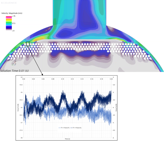
Figure 1:
CFD force time history for a single tube.
In parallel, modal analysis and stead-state dynamics were performed using FEA. The tube natural frequencies and impingement plate modes were identified so that the structural response could be understood in relation to the CFD-derived excitation (Figure 2). This is where the coupling between CFD and structural assessment becomes most important. The CFD does not merely provide a flow picture; it provides the forcing spectrum. The FEA modal analysis does not merely provide mode shapes; it provides the transfer characteristics that determine how strongly the structure responds to that forcing. When excitation energy overlaps with structural modes, the resulting vibration response and fatigue damage can increase significantly.
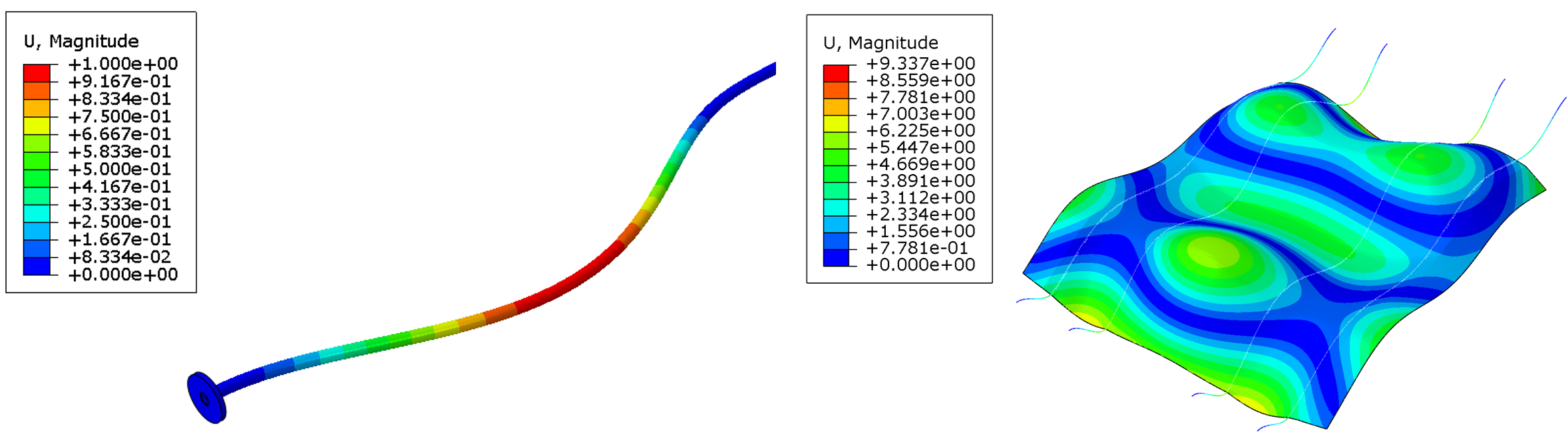
Figure 2: Modal analysis of tube and impingement plate.
The critical step was converting the transient CFD force histories into Power Spectral Density, or PSD, inputs. This moved the problem from a time-domain description of fluctuating forces into a frequency-domain description of energy content. That distinction matters. A traditional time-history fatigue calculation requires explicit stress histories and sufficiently fine temporal resolution, followed by rainflow counting. For a complex system with many structural modes and broadband excitation, that can become computationally expensive and difficult to interpret. A PSD-based method allows the same random vibration problem to be assessed more efficiently while retaining the frequency content that drives fatigue. The PSD for the critical tube is shown in Figure 3.
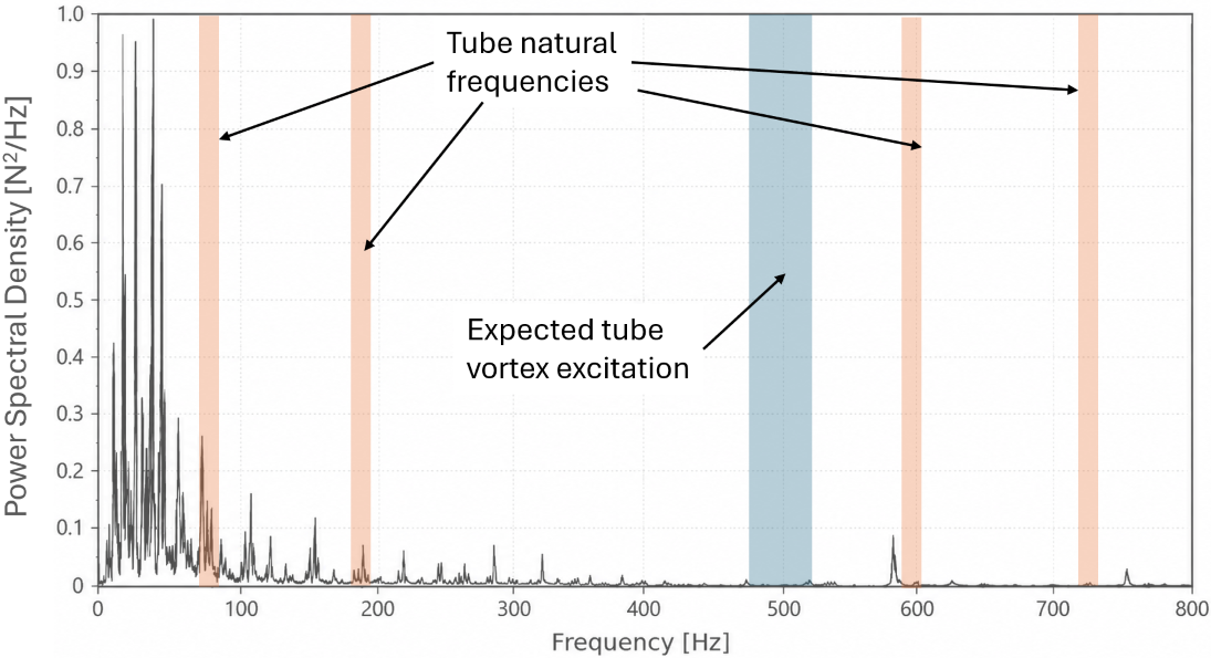
Figure 3:
PSD for the critical boiler tube.
The fatigue assessment was carried out in fe-safe and combined three core inputs: the FEA modal results, the CFD-derived PSD, and the material S-N fatigue curve. A steady-state dynamics frequency sweep analysis was used to calculate the output stress PSD at critical locations. From there, a statistical rainflow estimate, such as Dirlik’s method, can be used to infer the expected distribution of stress ranges from the output PSD. Fatigue damage is then accumulated by comparing the expected stress cycles against the material fatigue curve. This provides a fatigue life without having to simulate a long-duration stress history directly in the time domain.
The baseline 73 TPH case showed low risk. The CFD results indicated that the overall PSD was minimal, with low energy in the fluid forces and no significant transients at the tube vortex shedding frequency. The assessment concluded that there was a low probability of flow-induced vibration of the tubes with subsequent fatigue calculations giving an estimated life exceeding 30 years.
The initially desired uprated condition of 82.5 TPH produced a very different result. The CFD indicated increased low-frequency excitation, broader excitation below 60 Hz, observable tube vortex shedding frequencies, and overlap with some tube structural modes. This combination increased the risk of fluid-induced vibration. When the CFD PSD was passed into the fatigue workflow, the predicted fatigue life fell to less than one year, which was clearly unacceptable for continued operation. An image showing the overall fatigue assessment workflow alongside the resulting fatigue lives for the 73 and 82.5 TPH conditions is shown in Figure 4.
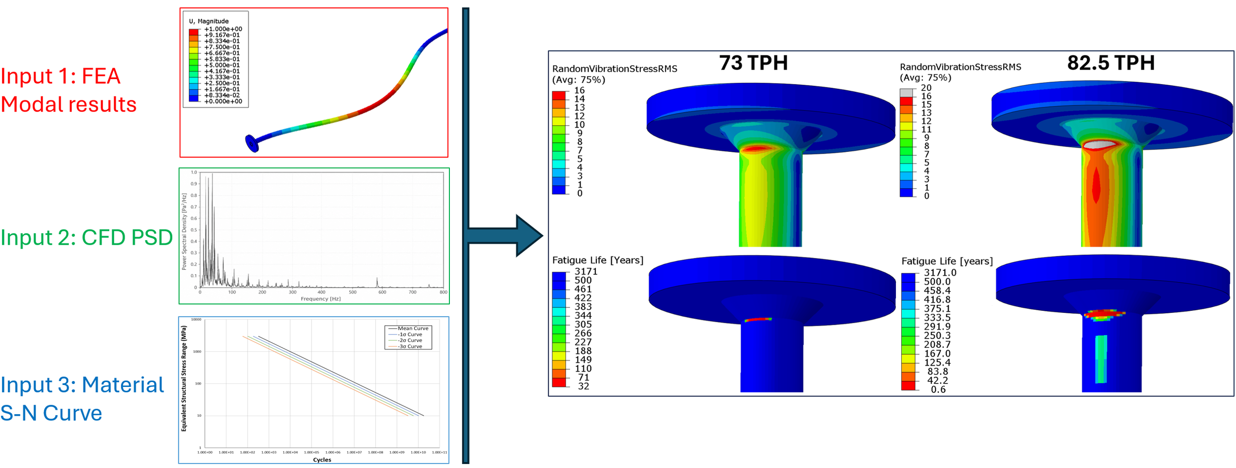
Figure 4: Fatigue assessment inputs and resulting fatigue lives.
An inlet modification option, using a straight inlet pipe at 82.5 TPH, was also considered. However, the analysis showed that this did not provide the required risk reduction. The frequency content became more tonal, strong tube vortex shedding remained, and excitation moved closer to a structural mode. As a result, inlet modification was discarded as the preferred mitigation route.
The final acceptable operating point was found at 75 TPH. This case still showed increased energy relative to baseline, but the fatigue assessment predicted a maximum RMS stress of approximately 17 MPa at the weld toe and a corresponding fatigue life of around 14 years. This allowed a modest uprate without requiring further modification to the inlet structure or impingement plate. Contour plots showing the fatigue lives for the three operating points are shown in Figure 5 and an X-Y plot showing the relationship between flowrate, RMS stress, and fatigue life is provided in Figure 6.
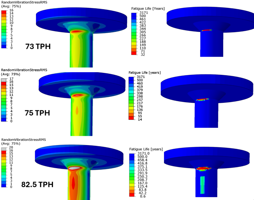
Figure 5:
Fatigue lives for considered operating points.
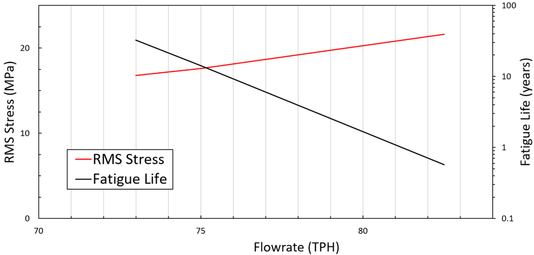
Figure 6: X-Y plot showing relationship between flowrate, RMS Stress, and Fatigue life.
The main lesson from this work is that CFD and fatigue assessment should not be treated as separate activities. CFD provided the realistic forcing environment; modal FEA determined the structural sensitivity; random-response and PSD-based fatigue methods converted that interaction into an engineering life prediction. Together, they enabled a defensible re-rating decision: 82.5 TPH was rejected due to unacceptable vibration fatigue risk, while 75 TPH was shown to provide a practical and supportable operating envelope.
For equipment operating in complex flow regimes, this type of integrated workflow offers a powerful route to decision-making. It goes beyond conservative screening and beyond visual interpretation of CFD alone. By linking transient flow simulation, spectral loading, structural dynamics, and fatigue damage, engineers can quantify risk and define operating limits with far greater confidence.