
Weld Peaking in PSA Vessels: The Hidden Integrity Risk
Pressure Swing Adsorber (PSA) vessels are critical components in industry, as these are used to remove impurities from hydrogen. These vessels undergo frequent pressurization and depressurization cycles, making fatigue performance a key design and integrity consideration. While fabrication standards often account for imperfections such as weld peaking (roof-topping) or ovality, the reality is that fabrication restrictions are not always fully adhered to. This can significantly reduce fatigue life and increase the likelihood of cracking. In this blog, we will be looking at the effect of this oversight during the vessel fabrication.
What is Weld Peaking?
Weld peaking refers to the out-of-plane distortion at welded joints, often occurring in long seams. Instead of maintaining a perfectly smooth transition, the weld area exhibits a local “peak” or “bump” in the vessel wall profile. This imperfection results in an increase in bending stress across the thickness. Fitness-for-service codes such as API 579:2021 [1] provide analytical solutions to calculate the increase in stress due to peaking. There are solutions for two peaking options (local and global), with the local peaking offering the most severe outcome. This subject was covered in my PVP paper from 2023 and in Revamps 2022 [2] [3]. In this current case, we will assume global peaking. This is because, from fabrication, the restriction in the drawings relates to roof topping, which aligns best with global peaking. However, the actual shape of the weld anomalies is best captured by laser scanning.
Design codes allow for limited peaking (in our current example, the drawing specifies 4.2 mm of roof topping). However, when laser scanning was carried out, the peaking was measured as 5.8mm.
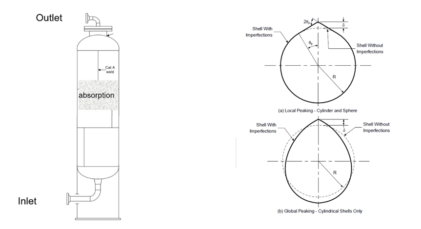
Figure 1.
Schematic of the PSA vessel (left) and global and local peaking as per API 579:2021 (right)
Why Long Seam Peaking Matters
In general, PSA vessels are fabricated from SA-516 Gr. 70, and the material is normalised resulting in good toughness even in a hydrogen environment. The vessels have typically been subjected to post weld heat treatment. The hoop stress range due to the pressure fluctuation is typical 100 MPa, not considering any peaking or other fabrication anomalies.
Assuming global peaking the effect in terms of additional bending stress across longitudinal seam weld is shown in Table 1. The assumption is a 35 mm thick wall vessel with 3,000 mm outer diameter.
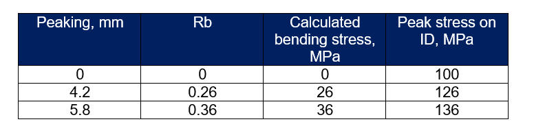
Table 1. Bending stress as a result of peaking
As can be seen in Table 1 the effect on bending stress due to peaking is significant. We will now look at what that means in terms of the expected fatigue life.
Fatigue Implications due to Weld Peaking
Using Structural Stress Methods from API 579 the corresponding fatigue life has been calculated taking account of the hydrogen environment and the internal pressure. The mean and design fatigue life for the three scenarios has been calculated and is shown in Table 2.
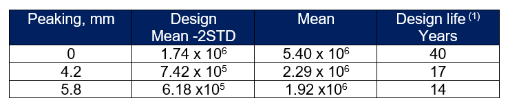
Table 2.
Number of calculated fatigue cycles for different level of peaking, Note: (1) Assuming a frequency of 12 minutes
From Table 2 even with the allowed level of peaking according to the fabrication specifications (4.2 mm) the design life is less than 20 years as typically required by the design codes. This indicates that despite the peaking restriction being specified on the general arrangement drawing, the PSA peaking or roof-topping was never considered during the original design. In addition, poor fabrication control indicates a further reduction in the original intended fatigue life from 17 years to 14 years. This means that cracks could initiate earlier than initially predicted from the design.
The Bigger Picture: Design vs Reality
It’s important to emphasize that even when PSA vessels supposedly are designed with peaking allowances in mind, the fatigue assessment in the above highlight that in certain cases the design does not meet a 20-year design life. On top of that additional challenge lies in fabrication quality and compliance. When vessel construction fails to meet the tolerances, the fatigue life reduces further increasing the risk of crack initiation well before the intended design life is reached.
This disconnect between design intent and fabrication practice underscores the importance of:
Stringent quality assurance during fabrication
Use of modern measurement tools (e.g., laser scanning) to verify compliance
Risk-based inspection strategies that consider realistic defect sizes and growth rates
Conclusion
Weld peaking may sound like a minor imperfection, but its impact on fatigue performance in PSA vessels is profound. While design codes accommodate some level of peaking, understanding the impact of longitudinal weld peaking and exceeding the fabrication limits significantly increases fatigue cracking risk. To ensure vessel reliability and extend service life, strict adherence to fabrication restrictions, robust inspection strategies, and proactive fatigue assessments are essential
References
The American Petroleum Institute and The American Society of Mechanical Engineers, " Fitness-for-Service API 579-1/ASME FFS-1 (API 579 Second Edition).," 2021.
A. Karstensen, "Life Management of Pressure Swing Absorbers," in Proceedings of the ASME 2023 Pressure Vessels and Piping Converence, Atlanta, 2023.
A. Karstensen, "Life or death of the PSA," Digital refining, November 2022.
A. Karstensen, Life managemnet of PSA vessels - Part 1 Measuring long seam weld peaking, https://becht.com/becht-blog/entry/life-management-of-psa-vessels-part-1-measuring-long-seam-weld-peaking/, 2024.